chipyard Customization
refrence_chipyard_Customization
笔者这里实在看不懂,看到一半give up了 有缘再看
RTL的generators
3.1 Rocket Chip
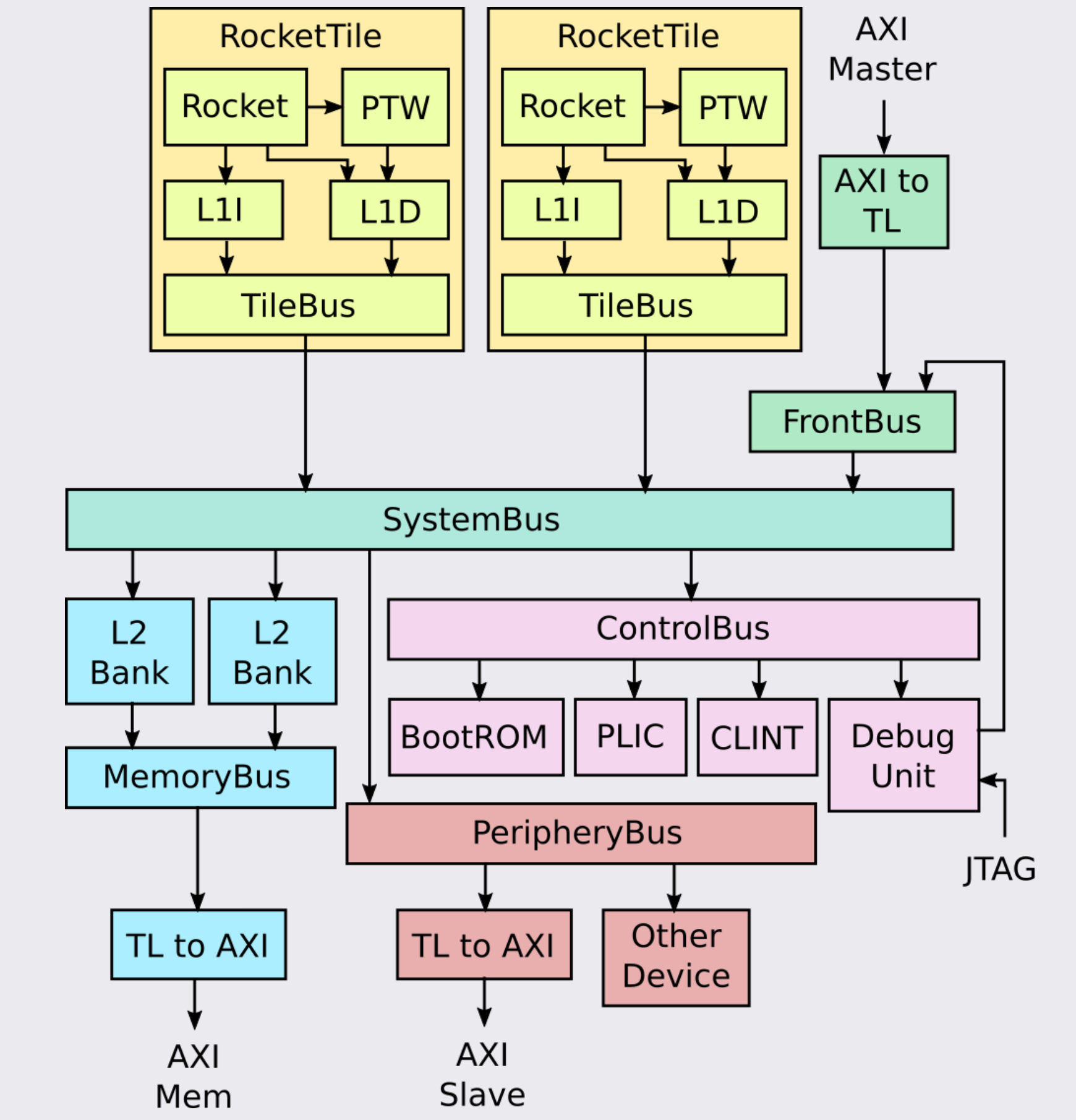
典型 Rocket Chip 系统的详细框图如下所示。
BootROM 包含第一阶段引导加载程序,即系统退出复位后运行的第一条指令。它还包含 Device Tree,Linux 使用它来确定连接的其他外围设备。
PLIC 聚合并屏蔽设备中断和外部中断。
PTW:page-table walker
使用虚拟地址,就涉及到将虚拟地址转换为物理地址的过程,这需要MMU(Memory Management Unit)和页表(page table)的共同参与。page table是每个进程独有的,是软件实现的,是存储在main memory(比如DDR)中的。
MMU是processer中的一个硬件单元,通常每个核有一个MMU。MMU由两部分组成:TLB(Translation Lookaside Buffer)和table walk unit
为page table设计了一个缓存TLB,CPU会首先在TLB中查找。TLB之所以快,一是因为它含有的entries的数目较少,二是TLB是集成进CPU的,它几乎可以按照CPU的速度运行。
TLB miss之后需要查当前进程对应的page table的时候,需要用到组成MMU的另一个部分table walk unit。在CISC和RISC中有不同的处理策略,通过CPU控制或者交给操作系统来处理
介绍一下 page table
CPU 中需要有一些寄存器用来存放表单在物理内存中的地址,SATP 寄存器会保存这个地址关系表单,这样,CPU 就可以告诉 MMU,可以从哪找到将虚拟内存地址翻译成物理内存地址的表单。当操作系统将 CPU 从一个应用程序切换到另一个应用程序时,内核会写 SATP 寄存器中的内容。所以,用户应用程序不能通过更新这个寄存器来更换一个地址对应表单,否则的话就会破坏隔离性。所以,只有运行在 kernel mode 的代码可以更新这个寄存器。
现在,内存地址的翻译方式略微的不同了。首先对于虚拟内存地址,我们将它划分为两个部分,index 和 offset,index 用来查找 page,offset 对应的是一个 page 中的哪个字节。将 offset 加上 page 的起始地址,就可以得到物理内存地址
一个page table一般是4KB,在物理内存中连续存在,物理内存是以 4096 为粒度使用的。所以 offset 才是 12bit,这样就足够覆盖 4096 个字节。 每个物理 page 的 PPN 是 44bit, 12bit 直接从虚拟地址的 12bit offset 继承就可以了
在某些使用的 RSIC-V 处理器上,并不是所有的 64bit 都被使用了,也就是说高 25bit 并没有被使用。这样的结果是限制了虚拟内存地址的数量,虚拟内存地址的数量现在只有 2^39 个(27bit index 12bit offset),大概是 512GB。当然,如果必要的话,最新的处理器或许可以支持更大的地址空间,只需要将未使用的 25bit 拿出来做为虚拟内存地址的一部分即可。在 RISC-V 中,物理内存地址是 56bit(这是由硬件设计人员决定的,预测物理内存在 5 年内不可能超过 2^56 这么大)。所以物理内存可以大于单个虚拟内存地址空间,但是也最多到 2^56。这样我们可以有多个进程都用光了他们的虚拟内存,但是物理内存还有剩余。
但是这样每个 page table 最多会有 2^27 个条目,进程需要为 page table 消耗大量的内存,并且很快物理内存就会耗尽,实际中,page table 是一个多级的结构。我们之前提到的虚拟内存地址中的 27bit 的 index,实际上是由 3 个 9bit 的数字组成(L2,L1,L0)
定义一个page directory为4KB,Directory 中的一个条目被称为 PTE(Page Table Entry)是 64bits,就像寄存器的大小一样,也就是 8Bytes。所以一个 Directory page 有 512 个条目。
所以实际上,SATP 寄存器会指向最高一级的 page directory 的物理内存地址,之后我们用虚拟内存中 index 的高 9bit 用来索引最高一级的 page directory,这样我们就能得到一个 PPN,也就是物理 page 号。这个 PPN 指向了中间级的 page directory。
当一个进程请求一个虚拟内存地址时,CPU 会查看 SATP 寄存器得到对应的最高一级 page table,这级 page table 会使用虚拟内存地址中 27bit index 的最高 9bit 来完成索引,如果索引的结果为空,MMU 会告诉操作系统或者处理器,抱歉我不能翻译这个地址,最终这会变成一个 page fault。如果一个地址不能被翻译,那就不翻译。就像你在运算时除以 0 一样,处理器会拒绝那样做。
当我们在使用中间级的 page directory 时,我们通过虚拟内存地址中的 L1 部分完成索引。接下来会走到最低级的 page directory,我们通过虚拟内存地址中的 L0 部分完成索引。在最低级的 page directory 中,我们可以得到对应于虚拟内存地址的物理内存地址。
实际的索引是由 3 步,优点是节省了巨大的条目空间。举个例子,如果你的地址空间只使用了一个 page,4096Bytes。除此之外,你没有使用任何其他的地址,在最高级,你需要一个 page directory。在这个 page directory 中,你需要一个数字是 0 的 PTE,指向中间级 page directory。所以在中间级,你也需要一个 page directory,里面也是一个数字 0 的 PTE,指向最低级 page directory。所以这里总共需要 3 个 page directory(也就是 3 * 512 个条目)。
剩下的一些
Gemmini项目正在开发一个全系统、全栈的DNN硬件探索和评估平台。
Saturn 是一款参数化 RISC-V 矢量单元生成器,目前支持与 Rocket 和 Shuttle 核心集成。 Saturn 实现了紧凑的短矢量长度矢量微架构,适合部署在 DSP 优化核心或面积高效的通用核心中。
IceNet 是与网络相关的 Chisel 设计库。 IceNet的主要组件是IceNIC,它是一个网络接口控制器,主要用于FireSim中进行多节点网络仿真。
Test Chip IP提供了设计 SoC 时可能有用的各种硬件小部件。其中包括SimTSI 、块设备控制器、 TileLink SERDES 、 TileLink 切换器、 TileLink 环网和UART 适配器。
6.1 定义core
1
2
3
4
5
class DualLargeBoomAndSingleRocketConfig extends Config(
  new boom.v3.common.WithNLargeBooms(2) ++             // add 2 boom cores
  new freechips.rocketchip.rocket.WithNHugeCores(1) ++  // add 1 rocket core(first ID)
  new chipyard.config.WithSystemBusWidth(128) ++
  new chipyard.config.AbstractConfig)
6.2 SoCs with NoC-based Interconnects
将片上网络集成到 Chipyard SoC 的主要方法是将标准 TileLink 基于交叉开关的总线之一(系统总线、内存总线、控制总线等)映射到 Constellation 生成的 NoC。
6.2.1 Private Interconnects
私有NoC的参数化,以及TileLink代理和物理NoC节点之间的映射
1
2
3
4
5
6
7
8
9
10
11
12
13
14
15
16
17
18
19
20
21
22
23
24
25
26
27
28
29
30
31
32
33
34
35
36
37
38
39
40
41
42
43
44
45
class MultiNoCConfig extends Config(
  new constellation.soc.WithCbusNoC(constellation.protocol.SimpleTLNoCParams(
    constellation.protocol.DiplomaticNetworkNodeMapping(
      inNodeMapping = ListMap(
        "serial_tl" -> 0),
      outNodeMapping = ListMap(
        "error" -> 1, "ctrls[0]" -> 2, "pbus" -> 3, "plic" -> 4,
        "clint" -> 5, "dmInner" -> 6, "bootrom" -> 7, "clock" -> 8)),
    NoCParams(
      topology = TerminalRouter(BidirectionalLine(9)),
      channelParamGen = (a, b) => UserChannelParams(Seq.fill(5) { UserVirtualChannelParams(4) }),//5个VC,bufferSize为4
      routingRelation = NonblockingVirtualSubnetworksRouting(TerminalRouterRouting(BidirectionalLineRouting()), 5, 1))//Virtual Network=5,为每个虚拟网络专用的虚拟通道数量为1
  )) ++
  new constellation.soc.WithMbusNoC(constellation.protocol.SimpleTLNoCParams(
    constellation.protocol.DiplomaticNetworkNodeMapping(
      inNodeMapping = ListMap(
        "L2 InclusiveCache[0]" -> 1, "L2 InclusiveCache[1]" -> 2,
        "L2 InclusiveCache[2]" -> 5, "L2 InclusiveCache[3]" -> 6),
      outNodeMapping = ListMap(
        "system[0]" -> 0, "system[1]" -> 3,  "system[2]" -> 4 , "system[3]" -> 7,
        "ram[0]" -> 0)),
    NoCParams(
      topology        = TerminalRouter(BidirectionalTorus1D(8)),
      channelParamGen = (a, b) => UserChannelParams(Seq.fill(10) { UserVirtualChannelParams(4) }),
      routingRelation = BlockingVirtualSubnetworksRouting(TerminalRouterRouting(BidirectionalTorus1DShortestRouting()), 5, 2))
  )) ++
  new constellation.soc.WithSbusNoC(constellation.protocol.SimpleTLNoCParams(
    constellation.protocol.DiplomaticNetworkNodeMapping(
      inNodeMapping = ListMap(
        "Core 0" -> 1, "Core 1" -> 2,  "Core 2" -> 4 , "Core 3" -> 7,
        "Core 4" -> 8, "Core 5" -> 11, "Core 6" -> 13, "Core 7" -> 14,
        "serial_tl" -> 0),
      outNodeMapping = ListMap(
        "system[0]" -> 5, "system[1]" -> 6, "system[2]" -> 9, "system[3]" -> 10,
        "pbus" -> 3)),
    NoCParams(
      topology        = TerminalRouter(Mesh2D(4, 4)),
      channelParamGen = (a, b) => UserChannelParams(Seq.fill(8) { UserVirtualChannelParams(4) }),
      routingRelation = BlockingVirtualSubnetworksRouting(TerminalRouterRouting(Mesh2DEscapeRouting()), 5, 1))
  )) ++
  new freechips.rocketchip.rocket.WithNHugeCores(8) ++
  new freechips.rocketchip.subsystem.WithNBanks(4) ++
  new freechips.rocketchip.subsystem.WithNMemoryChannels(4) ++
  new chipyard.config.AbstractConfig
)
6.2.2 Shared Global Interconnect
配置片段仅提供 TileLink 代理和物理 NoC 节点之间的映射,while a separate fragement provides the configuration for the global interconnect.
6.5 ROCC和MMIO
将加速器或自定义的IO设备加入SOC:MMIO或ROCC
通过 TileLink-Attached 方法,处理器通过内存映射寄存器与 MMIO 外设进行通信
处理器通过自定义(custom)协议和 RISC-V ISA 编码空间中保留的自定义非标准 ISA 指令与 RoCC 加速器进行通信。每个内核最多可以有四个加速器,这些加速器由自定义指令控制并与 CPU 共享资源。 RoCC 协处理器指令形式为:customX rd, rs1, rs2, funct
X 是数字 0-3,决定指令的操作码,它控制指令将路由到哪个加速器。 rd 、 rs1和rs2字段是目标寄存器和两个源寄存器的寄存器号。 funct字段是一个 7 位整数,加速器可以使用它来区分不同的指令。
通过 RoCC 接口进行通信需要自定义软件工具链,而 MMIO 外设可以使用该标准工具链以及适当的驱动程序支持。
RoCC 加速器通过扩展LazyRoCC类的模块进行实例化,下面是 RoCC 加速器的最小实例
1
2
3
4
5
6
7
8
9
10
11
12
13
14
15
16
17
18
19
20
21
22
class CustomAccelerator(opcodes: OpcodeSet)//opcodes是映射到此加速器的一组自定义操作码
    (implicit p: Parameters) extends LazyRoCC(opcodes) {
  override lazy val module = new CustomAcceleratorModule(this)
}

class CustomAcceleratorModule(outer: CustomAccelerator)
    extends LazyRoCCModuleImp(outer) {
  val cmd = Queue(io.cmd)
  // The parts of the command are as follows
  // inst - the parts of the instruction itself
  //   opcode
  //   rd - destination register number
  //   rs1 - first source register number
  //   rs2 - second source register number
  //   funct
  //   xd - is the destination register being used?
  //   xs1 - is the first source register being used?
  //   xs2 - is the second source register being used?
  // rs1 - the value of source register 1
  // rs2 - the value of source register 2
  ...
}
LazyRoCC类包含两个 TLOutputNode 实例:
atlNode:connects into a tile-local arbiter along with the backside of the L1 instruction cache.
tlNode:连接到L1-L2 crossbar
加速器可用的其他接口是mem ,它提供对 L1 缓存的访问; ptw提供对页表遍历器的访问; busy信号,指示加速器何时仍在处理指令;以及interrupt信号,可用于中断CPU
示例 generators/rocket-chip/src/main/scala/tile/LazyRoCC.scala 有关不同 IO 的详细信息。
